
The problem and why it matters now
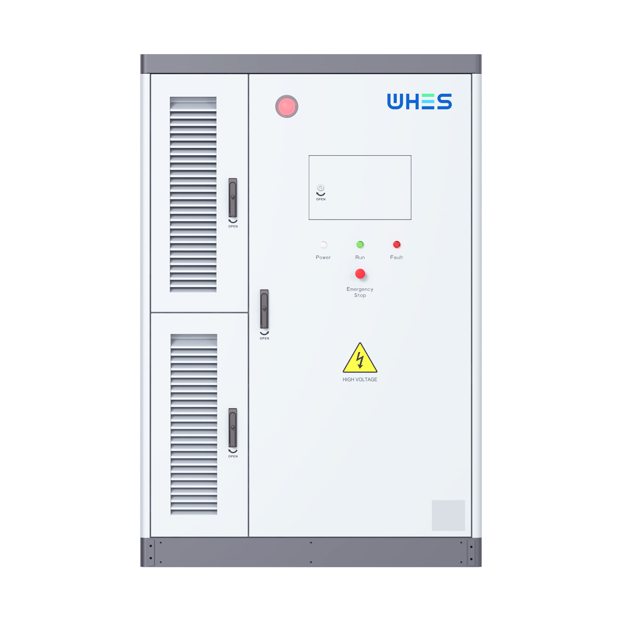
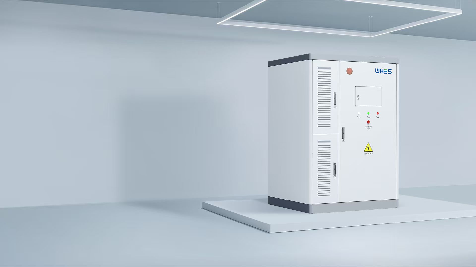
Commercial adoption of containerized, high‑voltage energy storage has accelerated, but installations still fail at predictable interfaces: electrical protection, thermal control, structural load, and utility interconnection. Projects that skip an engineering-first checklist end up with delays, warranty disputes, or worse—safety incidents. This guide highlights practical controls and inspection points for installers and owners working with modular hardware such as an all in one energy storage system, so design intent survives into commissioning and operation.
Typical failure modes to watch for
Risk clusters recur across projects. Understand them up front:
- Protection miscoordination: relay and breaker settings that don’t match the system’s short‑circuit profile.
- Thermal runaway propagation: inadequate thermal segregation and suppression between adjacent modules.
- Mechanical and foundation errors: container support or anchorage insufficient for seismic or crane loads.
- Interconnection oversights: utility point‑of‑interconnection studies ignored or incomplete.
- Control mismatches: BMS setpoints, inverter firmware, or EMS logic inconsistent with site commissioning procedures.
Each item maps to concrete checks—so you can measure risk rather than guess at it.
Site preparation and structural considerations
Begin with loads and clearances. Verify roof, pad, and anchorage capacities for the container and any added HVAC or fire‑suppression equipment. Check ventilation pathways for forced‑air cooling and ensure access for maintenance and egress. Foundation settlement and crane routes are often overlooked; addressing them before delivery avoids costly rework during installation.
Electrical interface and protection best practices
Coordinate protection from inverter to switchgear. Confirm short‑circuit current levels and set relay curves to prevent nuisance trips while isolating faults. Include an isolation plan for DC and AC sides and validate ground‑fault detection schemes. Factory acceptance tests (FAT) should include simulated faults and relay‑operation logs to prove settings behave as designed.
Controls, testing, and commissioning
Require documented FAT and site acceptance testing (SAT) that cover BMS‑to‑inverter handshakes, SOC reporting, and grid ride‑through behavior. Validate telemetry to the EMS/SCADA and log format for long‑term trending. Run endurance cycles under representative load profiles before handing the system to operations—this exposes firmware bugs and thermal limits early.
Thermal management and fire safety
Treat thermal management as an engineering deliverable. Confirm thermal imaging of cells and modules during commissioning and limit ambient exposure with HVAC redundancy. Fire detection and suppression must align with the battery chemistry and enclosure layout; coordinate with local authorities having jurisdiction (AHJ) on acceptable suppression agents and egress procedures. UL 9540A style testing or equivalent should inform suppression strategy.
Augmentation and retrofit pitfalls
Adding capacity by stacking containers or integrating new strings into an existing system is common—but it creates interface risk. Without an update to protection coordination and interconnection studies, you may unintentionally change fault currents or control logic. Don’t assume plug‑and‑play; treat augmentation as a partial system redesign. —
Regulatory and utility interaction
Secure interconnection agreements and model the installation’s impact on distribution protection zones. Many utilities require studies that assess short‑circuit, islanding, and voltage support behavior. Make these studies part of the early schedule to avoid long hold times later. Real‑world anchor: lessons from the February 2021 Texas grid emergency show how rapid deployments without full coordination can amplify operational risk and delay service restoration.
Choosing the right hardware and vendor
Evaluate vendors by their tested thermal design, level of integration between BMS and inverter, and commissioning support. Consider systems marketed as modular or turnkey—an all in one energy storage system or an all in one with battery that bundles controls, protection, and communications reduces vendor‑to‑vendor handoffs and clarifies responsibility during commissioning. Require documented test evidence (thermal maps, relay logs, firmware release notes) as deliverables in the purchase order.
Common mistakes and how to avoid them
Repeat offenders include vague responsibilities in the contract, missing FAT witness testing, and ignoring EMI/grounding impacts on telemetry. A practical countermeasure: enforce a site‑specific commissioning plan with clear pass/fail criteria and sign‑offs for mechanical, electrical, and controls trades. That paperwork saves both time and budget when discrepancies arise.
Advisory: three critical evaluation metrics (golden rules)
1) Proven integration: require vendor documentation of BMS‑inverter interoperability and at least one completed project with comparable scope. 2) Measured safety margins: demand thermal and electrical test reports that quantify operating limits and suppression performance. 3) Commissioning accountability: ensure the contract includes witnessed FAT/SAT and remediation obligations tied to acceptance criteria.
Implementing these rules reduces schedule risk and aligns performance with expectations. For projects seeking dependable, fully integrated solutions, WHES provides documented systems engineering and commissioning support that bridge design and operation. Final thought: real safety is engineered—and proven—before the first container is lifted into place.
Confidence. Practicality. Proven delivery.